BMT2 was a near-field model of fractured rock of a size 0.75 m in horizontal length and 0.5 m in vertical height, containing four perpendicular fractures, as smooth parallel fractures, cutting the model into nine blocks (Fig.3a). An initial temperature t° = 15° C and initial horizontal and vertical stress components = - 4 MPa were assumed, with the factures having a constant aperture of 300 micrometers. The aim of BMT2 was to investigate the coupled behavior of fractures and intact rock matrix in fully coupled THM processes, including optional consideration for forced heat convection along the fractures. Five research teams participated in BMT2 (see Table 2), using different numerical computer codes and numerical methods: MOTIF (FEM by ARCL), UDEC (DEM by CNWRA and INERIS), ROCMAS (FEM by LBL) and ADINA-T/JRTEMP (FEM by VTT). Figure 3b and 3c show two examples of the simulated results of displacements and water head at monitoring locations.
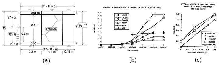
Besides the achieved aim of comparing performance and relative validation of computer codes and models for such a near-field problem with explicit representation of fractures, the other main scientific/technical findings include the significant differences caused by the thermal convection by water flow in the fractures, importance of thermal expansion inside the host rock far from repository or near ground surface, and the dominating fracture closure under confined mechanical conditions during heating and thermal expansion processes. The main outstanding issues included: importance of the mechanical behavior generated by discrete and continuum models that require further study on the fundamental aspects of the numerical modeling using different material characterizations of fractured rocks, and not achieving a realistic model set-up with too small a power input and over-constrained boundary conditions—leading to a less realistic mechanical behavior of the model.
TC1 was based on a laboratory experiment, conducted at NGI (Norwegian Geotechnical Institute, Oslo, Norway), for coupled stress-flow processes in a rock fracture (Fig. 5a). The sample of the fracture was created as a large diameter core containing a single fracture under multiple stepped loading–unloading cycles while water was conducted through the fracture. The normal and shear stresses and displacements, as well as flowrate, were measured during the test. Modeling of TC1 was conducted in two steps: TC1:1 and TC1:2. TC1:1 modeling was first carried out using the simplified model set-up of the test system, as shown in Fig.5b, but it was found out that the stiffness of the test frame adopted in the TC1 model was not adequate to produce reliable results. Therefore, the model set-up was developed to represent the complete test frame including all parts, as shown in Fig. 5a, called TC1:2.
Four research teams participated in TC1:1: CNWRA, ITASCA (Sweden branch) and NGI using code UDEC of DEM, and LBL using code ROCMAS of FEM. Three teams participated in TC1:2: AECL using code MOTIF of FEM, LBL using the code ROCMAS of DEM, and NGI using the code UDEC of DEM.
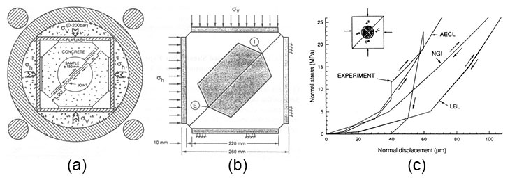
The results demonstrated that TC1:2 much improved the model development, with reasonable agreement between normal stress-normal displacement for loading paths, but less agreement for the unloading path, indicating inadequate ability to represent the stress-path dependence of the constitutive models of the fractures in the codes applied, which, in turn, led to inadequate agreement between measured and calculated hydraulic aperture, mechanical and hydraulic apertures, measured and calculated shear dilation. These findings caused significant concern in the project— such that coupled THM processes of single rock fractures became a continued issue of research and discussions in the subsequent phases of the DECOVALEX projects.
TC2 was defined so as to simulate an intermediate scale in-situ heating test of a host rock at the Fanay-Augères test site, France, with coupled thermo-mechanical processes, for the unsaturated in-situ condition and small permeability of the fractures. The objective was to develop validating the abilities of numerical modeling to simulate 3D fractured rocks under combined heating and mechanical loading/unloading conditions. Figure 6 shown the layout of the test site geometry (Fig. 6a), locations for installing extensometers for monitoring the displacement field (Fig. 6b), and the results of evolutions of normal displacements at an extensometer borehole EF2 (Fig. 6c).
Three teams participated in TC2, using different numerical methods and computer codes: INERIS (supported by ANDRA, using code 3DEC of DEM), ENSMP (supported by IPSN, using code VIPLEF (with different elements (4-noded and 10-noded) of FEM), and CLAY (supported by SKB, using code ABAQUS of FEM) and all models were set-up in 3D, concerning coupled TM processes.
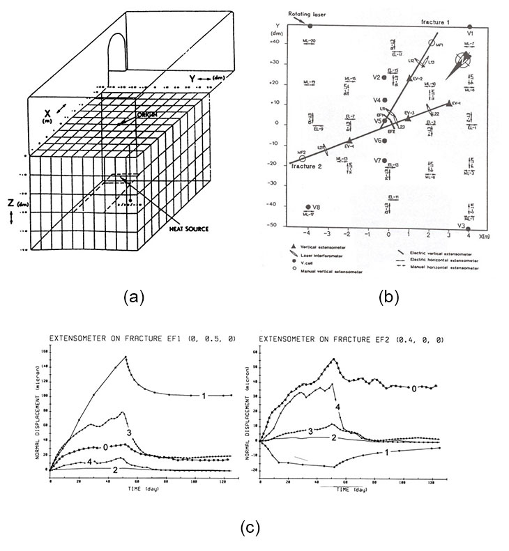
It was found that both modeling approaches of the equivalent continuum (FEM models) and the discrete system (DEM model) were able to simulate the coupled TM processes in a fractured rock mass. However, the main difficulty was being able to adequately represent the 3D problem geometry (the mesh generation being a main challenge) and properly developing the constitutive models of the fractures. There were divergent results, such as extension of fractures, which diverged due to the different assumptions and model parameters applied, despite the fact that the calculated temperature field agreed well with measured data, and the predicted floor heaving by the models had a qualitative agreement with the measured data. The results indicated that more comprehensive and reliable constitutive models of rocks incorporating fully coupled THM processes are needed for future research and more improvement of computational capacity for 3D problems at site scales.
TC3 was defined based on a large scale laboratory experiment of the coupled THM processes of the engineered barrier system for GDRW, using the BIG–BEN (Big–Bentonite) facility at the Tokai Works, PNC, Japan. The aim of TC3 was to test and compare the capabilities of different numerical models and computer codes for simulating one of the test pits based on the current design. Figure 7a illustrates the BIG–BEN test facility with different components, and Figure 7b shows the test pit geometry and some monitoring point locations. Three research teams participated in TC3 and used different modeling approaches: CLAY (supported by SKB), CNWRA (supported by NRC, using code ABAQUS of FEM), and KPH (supported by PNC CNWRA (supported by NRC, using code THAMES of FEM). All teams used 2D axisymmetric models, but with different element types (4-noded and 8-noded) and mesh resolutions. Figure 7c and 7d show the results of the calculated and measured temperature and water content at different monitoring locations.
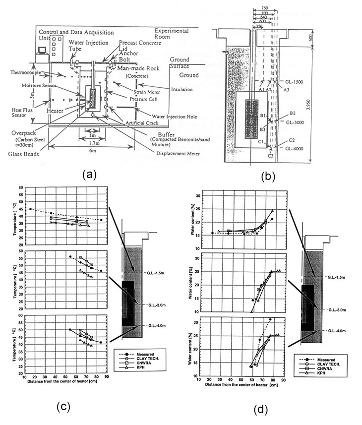
The main findings were that the calculated results of temperature and water content agreed well with the measured data, but not the stress values among the teams, which may have been caused by different treatments of the swelling pressure phenomenon of the bentonite, and inadequate mechanical constitutive models for the bentonite materials.
TC4 was originally designed and implemented as a potential Test Case of the DECOVALEX I project concerning the coupled hydro-mechanical processes of single rock fractures under controlled laboratory test conditions, carried out at Helsinki University of Technology and supported by VTT. The test was conducted using a MIT 815 Rock Mechanics Test System with servo-controlled mechanical loading and temperature controlled chamber with a rock sample of 102 mm in diameter and 100 mm in height, containing one single fracture for fluid flow, under an axial load of 80 MPa, a confining pressure of 10–16 MPa with loading rate varying from 0.1 to 08 MPa/sec and a flow rate of 0.05 cm3/sec for 600 seconds. Heating was not included in the test. Figure 8a shows an illustration of the tested sample chamber and the rock fracture sample, and Figs. 8b and 8c show results of fracture conductivity vs. effective stress for sample number 2111A and 2411B, respectively.
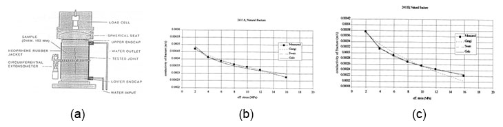
Unfortunately, no numerical simulations were conducted due to the fact that delays in the final test schedule and resulting assessments meant that the test could not be simulated by the research teams within the project’s schedule.
TC5 was another laboratory experiment on coupled hydro-mechanical processes in a single rock fracture, conducted at ANWRA (Center for Nuclear Waste Regulatory Analysis), Southeast Research Institute, San Antonio, TX, USA, using ANWRA’s direct shear test frame. Figure 9a show the schematic set-up diagram for the direct shear test of linear fluid flow with normal and shear loading arrangements. A series of linear fluid flow tests under combined normal stress loading with values 1.0 MPa, 4.0 MPa, 5.0 MPa and up to 8 MPa, and a shear displacements up to 25.4 mm, were conducted. Figure 9b shows the results of hydraulic conductivity and normal displacement vs. shear displacement as measured during the test under a normal stress load of 2.0 MPa—as one of the examples of the measured data.
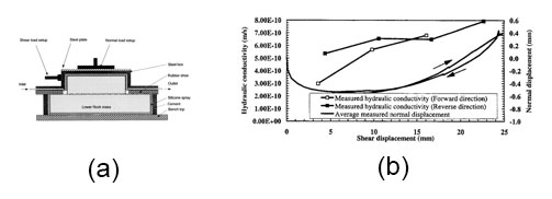
Similarly to TC4, no numerical simulations could be performed for TC5 due to the delays caused by further test equipment development and test schedule changes.
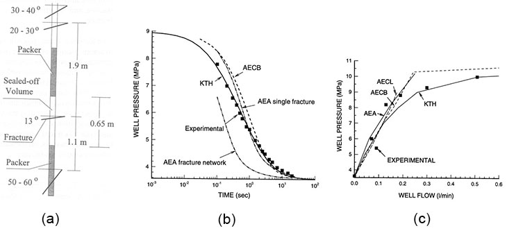
TC6 was defined for numerical modeling of an in-situ field injection experiment of a sub-horizontal fracture conducted in a borehole of 56 mm in diameter at Luleå University of Technology, Sweden, in 1992 during the early stage of this DECOVALEX I project. The Test Case addressed the role of coupled hydro-mechanical processes of water injection effects on the behavior of a sub-horizontal fracture located at a depth of 356–7 m below the ground surface, with the section of the borehole containing the fracture isolated by pressurized packers (see Fig.10a). A series of three types of injection tests were conducted: pressure pulse test, step pressure test (hydraulic jacking), and constant pressure injection test with a pressure exceeding the overburden pressure. The TC6’s objective was calibration of numerical models against the measured field test results, with targeted calibration of Young’s modulus of the host rock, initial hydraulic aperture of the tested fracture at the initial stress state, type and location of the outer boundary of the tested fracture and effective normal stress as a function of normal displacement of the tested fracture.
Five research teams participated in TC6 with different computer codes and numerical methods: KTH (supported by SKI) using the code ROCMAS of FEM, AECB (self-supporting) using the code FRACON of FEM, AECL (self-supporting) using the code MOTIF of FEM, AEA (supported by NIREX and CEC) using code NAPSAC of DFN and LTH (Lund University, Sweden, supported by SKB), using analytical solutions. Figures 10b and 10c show the results of measured and calculated well pressure variations vs. time and well flow, respectively.
The TC6 modeling was in good agreement with the measured data, with the differences mainly caused by slight differences in parameters, such as the initial values of the fracture properties, and possibly also the effects of the fracture size estimations. TC6 showed that, for injection pressure below the virgin stress normal to the fracture plane, the coupled hydro-mechanical process of the fracture dictated the pressure-flow responses, and the key parameters were the hydraulic aperture, normal stiffness and effective normal stress of the facture.