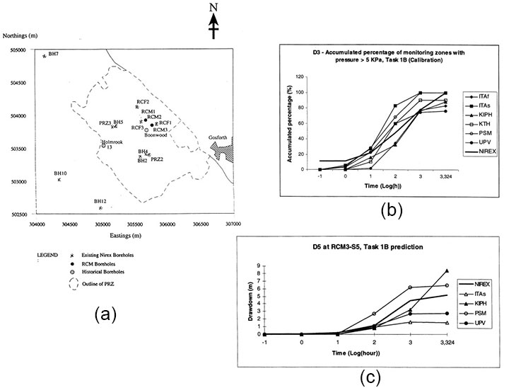
Task 1 consisted of two steps of three phases:
Seven research teams participated in Task 1A and Task 1B, with their numerical modeling approaches described in Table 1 below.
| Team | Basic model features |
| ITAf | DFN (1D random pipe(channel) network for in 3D space) , code 3FLO, flow only |
| ITAs | FDM, Equivalent continuum, 2D-axisymmetric model centered around FCF3 borehole |
| KIPH | FEM, equivalent continuum, 3D model containing faults, codes SISIM & SETRA |
| KTH | DFN, 3D, flow only through 7 faults solved by FEM, codes FRANMAN and MAFIC |
| PSM | DFN, 3D, coupled stress-flow process, code FRACAS |
| UNEW | FDM, equivalent continuum. 3D stress-flow coupling, code PARADIGM |
| UPV | FDM, fractured continuum, 3D, codes GCOSIM3D, ISIM3D, INVERTO |

Six teams participated in Task 1C, with their numerical modeling approaches described in Table 2. Only blind numerical predictions were performed without calibration, due to a the fact that the continuation of the RCF program at Sellafield site was halted, including the Nirex’s shaft excavation project.
| Team | Basic model features |
| ITAs | FDM, faulted equivalent continuum, 3D, code FLAC3D, uncoupled H- & M-processes |
| KIPH | FEM, equivalent continuum, 3D model containing faults, code THAMES |
| KTH | FDM, 3D, code FLAC3D, M-process only, no EDZ considered |
| PSM | Uncoupled H- & M-process, FEM for stress analyses (code VIPLEF), DFN for fracture flow (code FRACAS) |
| UPV | FEM, fractured continuum, 3D, codes ANSYS, GCOSIM3D, ISIM3D, and INVERTO. No EDZ |
| VTT | Uncoupled H-& M-processes. 3D, FDM (code FLAC3D) for stress analysis, DFN (code TRINET) for fracture flow. No EDZ. |
Task 1A and 1B were successfully carried out with quite a diverse combination of different modeling approaches, numerical methods and computer codes, and material characterization schemes. The large amount of site characterization/investigation information enabled more reliable numerical modeling, which led to reasonable results for modeling the pressure field and the general trend of the flowrate data, as demonstrated by a number of published journal papers. However, significant uncertainties stll existed, which related to flow properties, characterization of field conditions based on reliable understanding, and use of the site investigation data for developing more reliable modeling approaches, especially model conceptualization concerning fracture systems given the huge amount of site investigation data.
For Task 1C, only blind predictions were performed since the shaft excavation could not be carried out, so that a logical discontinuity existed between Task 1A+1B and Task 1C. However, efforts were made by the Task 1C teams, helped greatly by the Nirex representative in the DECOVALEX project, to establish possible links between Task 1B and 1C using the site investigation information available. As a result, useful modeling was conducted for understanding the effects of the coupled stress-flow processes of the BVG caused by shaft sinking, especially on the EDZ phenomenon at a time when the EDZ issue was just started to be considered more widely and comprehensively in the international community of GDRW.
The main outstanding issue of Task 1 was the need for more in-depth research on characterization of the site geology and the physical and chemical processes—as the basis for more successful and reliable numerical modeling of coupled THM or THMC processes, especially for fractured crystalline rocks, such as the BVG at Sellafield, UK.